Total Pageviews

Thursday, September 20, 2012

axle link brackets & links v2

Ever notice that work on this thing comes in waves?
 
Everything just barely fits without removing all of the scouts leaf spring perches.
The scout stuff doesn't hang down low enough to be a problem, so why chop it?
IF, and I mean IF a reason to change axle happens by- these can still be sold to a scout owner
and all they need to do is chop the brackets off.


After that, a few skid plates were in order to protect the links
and strengthen it.
 
FYI- I weighed the lower brackets and coil springs before installation- 23 lbs each side.
So this will altogether weigh more than a leaf spring setup.
(lower links are going to be 14 lbs ea. by themselves)

A better picture...

Passenger side finished- it is *really* tight because of the caliper at full steer.
The only jack point on this side is the original scout 
spring perch because it is so tight and the angle of the bracket skid plate.

The drivers side has a little more wiggle room without the pumpkin to
work around.
Note the fancy alignment device- a screw on one side and
a nut on the other.
------------------------------------------------------------------- 
 
Here's the mock up of the lower link.  Its about 32" long
and has about a 15* bend in it.  I taped a straight piece
to it to keep it inline while measuring.  Simple- right?

Now- how to break a $300 bending die. ( just the die, not the bender price)
Set up- pre carnage with 0.25" dom 4130
 
 
The 0.25" wall tubing was supposed to be brought around by the
curved part of the die ( above the degree wheel)
The tubing is so strong that the clamping area broke off as the die turned
and ripped the clamping area out of its weld.
Listen to the sound and watch the vice grip pliers at 14 seconds.
Didn't even bend the tube 1*.
-------------------------------------------------------------
poof, got the tubes bent- I had to chop saw through the tube wall barely
in 2 places to make it weak enough for the bender to have a chance and weld a
gusset plate onto the die.
These slots in the tubing were welded back shut afterwards.
I give you- 17 lbs of oomph.


 Link installed to rear

Link installed to axle
!!!!!!!!!!!!!!!!!!!!!!!!!!!!!!!!!!!!!!!!!!!!!!!!!!!!!!!!
Big change coming up on 4 link design-
The radius arm setup will be tight- really tight but plausable.
The outer frame 4 link is a no go because the tire will rub the upper control arm.
So a triangulated upper link is going in place from the inside of the frame above
where the spring hanger was, to the center of the front axle.
Due to the geometry of this, I will not need a track bar now! :)
 
The original upper tab links are going to be where the shock will mount now.
 
I typed this into the ranger stations 4 link calculator and everything came out great
 Gotta order another big heim joint, and may just truss the front at the same time!
 
 --------------------------------------------------------------------------
I'll give you a hint- its not ice cleats.
 
Upper 4 link mount
 
Various parts


looking from driveshaft side...
The extra plates will weld from the bracket straight to the
axle tube.  There's also a top support plate to tie it all together.
 

Sunday, September 2, 2012

steering v2

hopefully the light isn't a train...
Chevy box on left, scout 2 box on right.
The chevy box (a saginaw model 83, the model 84 is the 3/4 and 1 ton version) mounts
almost the same as the jeeps, the scout mounts outside of the frame
(pitman aims towards the front-stock)
What do they have in common? see pic#3

 Here's the jeep pitman arm hole

Here's the scout AND chevy pitman arm hole

Chevy -left- having compensation issues vs the scout
The scout and chevy seem to have similar sized tie rod ends.

 With this much droop, why am I doing coils again??
oh yeah- turning radius and stability
 
Its time to check all the parts while I'm doing this.
Rear spring bolt upper, shackle side lower
Both are grooved into by the shackles and hangers
 
 
9-5-12
It's A: amazing and B: scary that four little bolts keep the steering box on.

Saginaw, meet saginaw.  Only about 21 years difference between the two.
Upper is manual jeep, on the bottom is power chebby w scout arm on it.
The chevy unit is 12" from input shaft to end of box.
I have to admit that I'm starting to like pre-govt bailout chebby stuff.
no wonder its so popular. The jeep splined input is almost the same size as the
chebby, but has smaller spines coming off the steering cup so no worky.
We'll have to use the chevy input shaft w/ rag joint. The previous scout box had a much bigger fine splined input.

This is the collapsable chevy steering shaft.  The left has a rag joint on it that goes
to the steering box.  The important thing is the upper piece of metal that slides in the shaft.


The part that collapses happens to be the same as the jeeps (upper)  so the end of the jeeps shaft must come off.  Either its cheap to build this way, or they got it right a long time ago.
Theres a spring that locks the rubber boot into the steering cup (right terminology?)
After that comes out the boot can be pulled back revealing this:

The part that fits into the cup. 
The posts coming off the jeeps shaft have a square block each on them with a retaining clip.
This fits into the cup and gives smooooth steering and durability.
(its almost 40 years old- proof enough)
After getting the axle under the jeep and figuring where /how the ps box will go ( fits original space pretty good btw) this will have to be hacked off and fit into the chevy shaft.
----------------------------------------------------------------
9-26
For clearance puposes and support, the tab on the chevy
box went into the jeeps crossmember.

Remember how it had an option of a power saginaw box?  The backside of the
crossmember was already notched for the models that came with power steering.

The box in place via jack

I cut maybe 5" off the jeeps steering shaft, and smoothed out the cut with
a flap grinding wheel.

This is , without a doubt, the easiest part of the whole conversion, nay the whole project. 
 Where the rubber boot starts is where the jeeps double d shaft is ending.
It slipped into the chevy piece about 5". 
There is still enough room for compression should the shaft need to though.
 
-----------------------------------------------------------------------
The final product 10-14-12
 
These are the original chebby steering hoses.  The metal part was unbent to fit around the radiator since it was so tight.  The return line was extended about 6" with some hose and works fine
since it is low pressure.
 

Saturday, August 25, 2012

suspension brackets and 4 link help v2

So how much is a piece of steel worth? I figure that $140 for these axle brackets / 4 hours (max) of my time = "free parts" basically $35/hr. ( I sure don't make that)
Having acess to a punch and plasma cutter help a lot. On right side of the picture is the frame coil bucket, on left side is suspension link / coil spring pad.
The savings are going for mucho sized bolts/ nylocks.  The big holes are 1" dia (12.49 per bolt and 8.23 per nylock) and the small holes are 9/16" all grade 8. sorry- mistyped original bolt price.
About $100 for grade 8 nuts, bolts, and washers.

 
9-17 ...and voila- the right side parts assembled and welded on the frame!  The brake line (hole to the right of the bracket) had a mounting bracket that  had to be chopped off and ground flat to mount this.
 

I'm hoping tomorrow to get the rear brakes bled - finally- and take the jeep around the block to see how the new rear gears feel. THEN I can park it backwards in the garage and start taking off the front axle and start installing all this stuff.
--------------------------------------------------------------------

Heres the basics for a four link design (still have to cut some parts for
the brackets, then I can start lopping off leaf springs)
http://www.therangerstation.com/Magazine/winter2007/4_link_tech.htm
I've read this 6 times and find something new on each reading. 
I used the 4 link calculator  (with update )at the bottom of the page
After punching in some factual and some close guesstimate measurements the suspension
 anti squat is at 95%  (read it- you'll understand).  If its possible to build the suspension like that- it'll work.

Here's what antisquat all comes down to: (big thanks for whoever made this)
The theoretical apex of the suspension links (the point under the block on above picture) determine whether your vehicle will squat or lift up when taking off depending on what side of the vehicles center of gravity its on.  Also how high it is. ( according to the article between 50 to 80% of the CG.)
This helps determines traction too. 
--------------------------------------------------------------
With a little more accurate measurements the program came up with a 96% anti squat, but the apex is 90% of the CG and about at the rear tires. 
The lower link is in front of the xfer case and the upper is in front of the body support on the side of the frame.  may have to do some tweaking to adjust this...
-------------------------------------------------------------------
9-16-12

 
Clean da frame to prep for welding

 
About at the front floorboards the frame rail goes from 2" wide to about 3".
crash protection??

inside of the passenger frame rail.  only half had to be cleaned because
the inside of the bracket comes up about an inch. (2.54 cm)

 
The outside plate and underframe plate were already welded together in a "t" formation. 
I bolted the big heim in place to align the holes of the inner (left with clamp on it)
 and outer holes.  This is the drivers side- note that 1/2" by 1" had to come off
the top of the inside plate to miss the transmission shifter linkage mount.
 Heim is 1.25" x 1" with 3/4" misalignment spacers.
Also had to loosen the exhaust and remove xfer skid plate for clearance.

The mini lincoln welder holds stuff in place until the old clarke welder hits it tomorrow.
 
There comes a time that the reality of how major an undertaking it is to do this- mine was welding the second bracket at arms length over the exhaust, around the transmission linkage, with my head in front of the engine oil pan just so I could see to weld.  Hope its worth it.
    

Sunday, August 12, 2012

transplant 1

We got home late and since this is the first time in 2 weeks that I get to sleep in tomorrow, I replaced the rear axle.  Somehow I managed to weld the spring perches on in the right place.   It went pretty smoothly, just need to make axle housing brake lines.  It doesn't seem that wide - until the tires went on.  Shiny "new" scout up, dirty old jeep axle lower.

The rear tires (upper near fan) used to stick out the same as the fronts (lower). Roughly 4" more on each side.   There's going to be some fender trimming in the future, and probably some fender flares.

Wednesday, August 8, 2012

coil springs methinks & front end parts

Moog cc875 variable springs made in USA!!! Woot!
5.3" outer dia , 17" unloaded height, 12" loaded height
spring load 680# (around there) 136 in/lb rate (per specs)
I balanced my healthy 215lb. self on one of these and it compressed about an inch.
I figured the leaf springs had to come off anyway just to move them 1.5" to match the axle so why not coils?


These are variable rate (meaning that they start easy to compress then become harder the more they are compressed ) and designed for a ford windstar which happens to be 3400#.
The commando started off life with a 258 at 3020# (the chevy 350 is the same weight)
 at a 60% front and 40% rear weight distribution, I'm figuring about 1800#
on the front end, minus a 350# ish axle, and 200# of tires of unsprung weight = 
 roughly 1200# and both coils are 1360#  (680*2=1360#)
Thus, if I misjudged the weight of the jeep (it could never happen) or a winch was added,
 there's enough overage. 
---------------------------------------------------------
8-19-12      I've got the brackets laid out on some 1/4" plate- just need to punch holes and cut them out.  In the meantime- I got overly serious and ordered some front end parts


Got a mix of dom bushings from barnes 4wd (hefty , no zerk options, but 1/2 to 5/8 of the price of some other places) 3" wide , can be chopped shorter if needed , 2" od.1.5 id dom, 1" od x 9/16 id inner sleeve.
The heims are roughstuff 1.25 x1" bore for the main lower link and 7/8 x 3/4 for the upper link.

Wednesday, June 20, 2012

return of the axles from differential gear v1.2

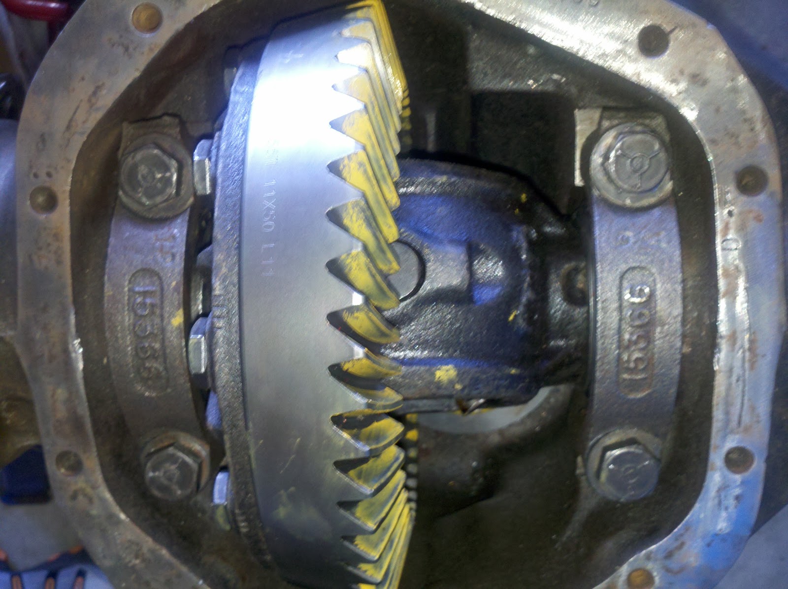
The gears finally showed up at the shop after a 4 day delay by the shipper.
  I trekked back to North Fort Worth to the shop where Charlie showed me two set up axles sitting on the floor.  It was hard to figure that they were the same ones that were dropped off- damn things had gears in them.
Although to some people (myself included) $600 is quite a drop in the bucket, it is still "cheap" compared to some shops for setting up axles.  (that was for both axles setup , a few extra bearings, and seals. btw)  I had already bought a master setup kit for one of the axles.

 I had a quote from one shop, for one axle, for $600 just for labor!!
Since they were carry in they were cheaper than still on the vehicle.

I went over to them and rotated the gears, perfectly centered pattern.  When holding the ring gear
I could turn the pinion to a slight click sound without moving the ring.  good backlash, now for
some heavy gear oil.


I had them done at:

Differential Gear
2519 NE 36th
Fort Worth, Texas 76111
817-222-9595

Ask for Charlie

the new 50/11 gears
in the rear with the
mini spool

The front
Total for rebuilt/regeared axles >$1K

Axles "free" (Even rebuilding a xfer case in swap for them, they ain't free!)
Wheel cylinders 50
spring perches 10
axle bearings 75
axle seals 30
gears 300
labor 475
master rebuild kit 110
paint 19
ball joints 100
And I'm sure something else will be needed.
7-3-12
The rear axle is assembled, ready to be stuffed in.  Needs a parking brake cable and new brake
lines on it.  Can be done in vehicle...
The front started going together- but the lower ball joints are keeping the steering knuckle from
seating- so waiting on scout brake hoses and lower ball joints. 
After that I'm STILL not sure if I want to leaf or coil spring it...

7-16  The parts were shipped on 7-5 and just arrived.  Anything Scout put one wrong number on the house address and the global giant UPS gets completely confused even after calling them 3 times.  Note to global giant- call my number that was on the package  to find out where to deliver it to ....duh.

The lower ball joints went in easier, much easier, than previous attempts.  The wrong size oreilly ones were about 1/2" taller than these and that's why part 41 wouldn't seat.  They came with zerks and a zerk plug, your choice luckily because the upper ball joints' zerk was too big to fit with the shaft in the axle.   so it got greased and got the plug.  The lower kept a zerk in it.

Make sure that before you start hastily putting the outer hub back together that the spindle seals are on first! (47,48,49) otherwise you'll be taking it back apart...really.


The only thing different about this diagram from the scout one is from part 55 would be the hub w/ brake rotor on it, then outer bearing w/ race, tabbed washer, large nut, thinner washer, large locknut, then warn hub assy.

v1.2
The axle is back together, hubs are cleaned and ready to put them on.
need tie rod ends.  I'm going to have to make a decision by the time the rear end goes on
on what to do with the front -coils or move the springs outboard to match the axle.